Meshing
We can technically make our Hello Kitty shirt using the already existing EA t-shirt. But what fun is that?! You are most likely reading this tutorial to learn how to really create custom clothing, and making you own meshes adds an extra kick to your creation!
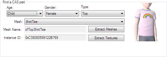
So now that we've decided which CAS part we are going to clone, it's time to extract some base meshes to build our custom mesh off of. Click Extract Meshes just under the CAS parameters. A window asking where to save your meshes will pop up. Choose whatever destination folder you want to save your work files in and click "Okay". You may close CTU for now.
I highly recommend you make an independent folder for all of your project work files, as CAS creation can get a little messy.
Looking where ever you saved your files, you should now see four new files:
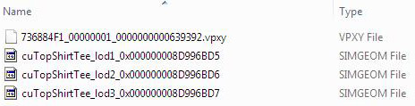
There are three SIMGEOM files and one VPXY file. You can discard the VPXY file as it is not used. The three .simgeom files are the three lod meshes of the shirt.
|
The word "lod" is an acronym that stands for level of detail. Lod 1 is the highest level of detail, where as lod 3 is the lowest. You will see lod 1 during normal - up close - gameplay. But when you are viewing sims from a distance or the game is still rendering sims, you will most likely see them in lod 2 or lod 3 form.
|
Multi Lod Meshes
Often times you may see meshes with multiple lod meshes:
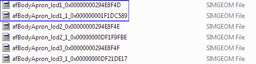
Never fear! This just means that the meshes come in parts. Usually lod1_0 is the main mesh and lod1_1 is something silly, like the index finger (dead serious). So you don't have to import both to edit the mesh. However this is a case-by-case thing, so you may or may not have to edit all the lod pieces.
Importing Meshes
Now that we have our meshes, it's time to start the physical meshing using our 3D Modeling program. Remember, you must have the GEOM import/export plugins installed in order to get the meshes into the modeling program. So, take a moment now to verify you have everything installed!
In Milkshape go to File -> Import -> Q Mesh Sims 3 Geom Importer. Let's navigate to our three mesh files and select the lod 1 mesh. A box saying "Unable to locate bone file. Default skeleton used." will pop up, simply click "Ok".
|
If you are greeted with...this..don't panic! You just need to adjust the joint size to something more suitable for TS3 meshes. Go to File->Preferences->Misc
Set it anywhere between 0.008 to 0.012 (less or more to your preference). Also, to ease confusion, go ahead and make the skeleton invisible by unchecking the "show skeleton" box on the Joints tab.
|
Blender users have a slightly different import/export procedure. Please read the instructions provided by the plugin coder or from the Blender website.
Scale/Move
Upon successful import, we should be greeted by our mesh. The method that we are going to use is the Scale and Move, the same method I demonstrated in my Quick Meshing video tutorials. The basic idea is that we are going to reshape our mesh by scaling and moving bits and pieces of the mesh, ONLY. That means absolutely under NO CIRCUMSTANCE should you add or delete polys/vertices from the mesh. The reason why is because the scale and move method allows us to create fantastically custom meshes, without having to create new moprhs for them, which is a pain.
Don't get me wrong, you can delete parts from meshes and even add new pieces from other meshes, this is called Frankenstiening. However, frankenstiening requires custom morphs to be made, as well as other intricate bits. So, that technique is best left for more advance creators, and will be covered in a separate tutorial. In short....Under NO CIRCUMSTANCE should you add or delete polys/vertices from the mesh. Are we clear?
So to begin our meshing, we want to get it into a workable view. Right-click on the mesh window and set it to a front projection (Projection->Front). To make it easier to see what we're doing, let's also apply a wireframe overlay to the mesh by right-clicking and selecting wireframe overlay.
I personally think that the torso of the female mesh is too square for a girl's frame, so I want to add a slight curve. To do this, I'm going to scale down the waist a bit.
We start by selecting a row of vertices, and click on the scale button. Make sure you have select-> by vertex chosen. In the three scale ratio boxes, we want to type .99 as the X and Z scale ratio.
|
Any scale ratio less than 1.00 will shrink the mesh, and vice versa with numbers greater than 1.00. A scale ratio of 1.00 itself, with keep the mesh neutral in that direction.
|
Since our scale ratio is .99, that means we are scaling in our mesh 1 percent [(1.00 - .99) x100] inward on the X and Z axis.
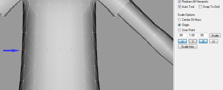
Notice how the Y axis's ratio is set to 1.00. This means that we won't be scaling the Y axis, which you want to avoid. Alternatively, you can just click the Y button to deactivate that scale ratio altogether.
|
The X axis scales/moves the mesh from left to right. The Y axis scales/moves the mesh up and down. And, the Z axis scales/moves the mesh from front to back..
|
Once you have decided on the row you want to scale and the appropriate scale ratio, click the smaller scale button (the one by the scale ratio boxes). Notice how our mesh has been pulled in slightly. Repeat this process until you get the shape you desire. Remember you can also use higher values, such as 1.01, to widen the mesh as you see fit.
After a little toying around, my mesh now has a slightly curved waist to fit a more girlish figure.
I also want to make my shirt longer, so I'm going to select rows of veritces (one-by-one) and pull them down until the shirt is the desired length.
To make sure you don't knock the mesh askew when pulling it down, you can set it to where you can only move the mesh in the Y direction. To do this click on the Move button, and deselect the X and Z button.
Since my shirt is now longer, I'll have to adjust to where it won't clip into pants and skirts. To do this open CTU and locate the child female nude mesh; follow the same extract/import procedures used earlier to get the mesh into Milkshape/Blender.Use this bottom mesh to gauge the proper size of the bottom of the shirt. You can show and hide this mesh under the groups tab to get it out your way when adjusting the shirt.
After you've gotten your mesh to your desired shape, you can just delete the bottom mesh from the groups tab.
You've done a third of the meshing already, so now is a good time to save!
Adjusting the UV Map
When you make drastic - or even slight - edits to a mesh, you'll need to adjust the UV map of the mesh. What exactly is a UV Map? well, it's basically information about the mesh that tells the game/program how to wrap the texture around it. If you have already done CAS creations, even small retexture, then you have seen the UV map in action - you just didn't know it! The easiest way to explain UV mapping, is to see it visually. But first, visit this thread by tiggerypum and download the templates-patternsforuvmap.zip file. Extract the two image files from the inside and drop them into your working folder.
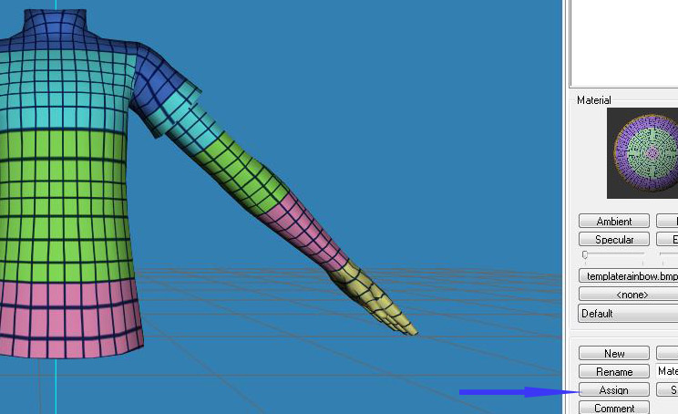
Back in Milkshape, we need to go to the Groups tab and click Select. Your mesh should now be highlighted in red. Next navigate to the Materials tab and click New. You'll see a little sphere pop up. Now click the first <none> button, and navigate to the rainbow checked pattern that we extracted from tiggerypums tutorial. Press okay, then hit "Assign". This assigns the rainbow texture to the shirt. If your mesh does not immediately show the checked texture, simply right-click -> Textured.
Ideally we want the checks to be distributed evenly on the mesh. Well, we can clearly see that there is stretching on the chest and at the bottom. Luckily this is easy to fix! However, whatever you do, do NOT create a new map.
Make sure that your entire mesh is still selected and open the Texture Coordinate Editor by hitting Ctrl + T. Alternatively, you can go to Window -> Texture Coordinate Editor.
When it pops up, you should see your mesh flattened on the rainbow texture. Before we touch anything, we want to Lock X position by checking the box. The prohibits us from accidentally knocking the UV map off center. Now, we need to select the rows of the SHIRT on the UV map where there is the distortion and move them up or down to make the checks uniform. Whatever you adjust on the mesh will be reflected on the mesh. I suggest having the mesh in 3D view while adjusting the UV map.
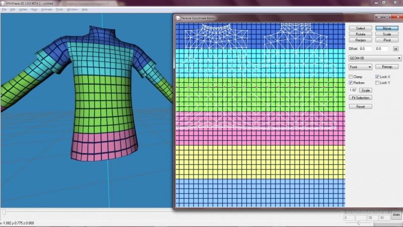
I adjusted the rows near where the stretching was on the chest - being careful not to mess up the arms mapping - to fix the stretching. Now, repeat to fix the bottom, or any other discrepancies you see.
After you've adjusted the UV map properly, it would be a good time to save!
Dem Bones
Get reference meshes, e.g. pants, skirts, dresses,etc.
Export
Lods
| 


